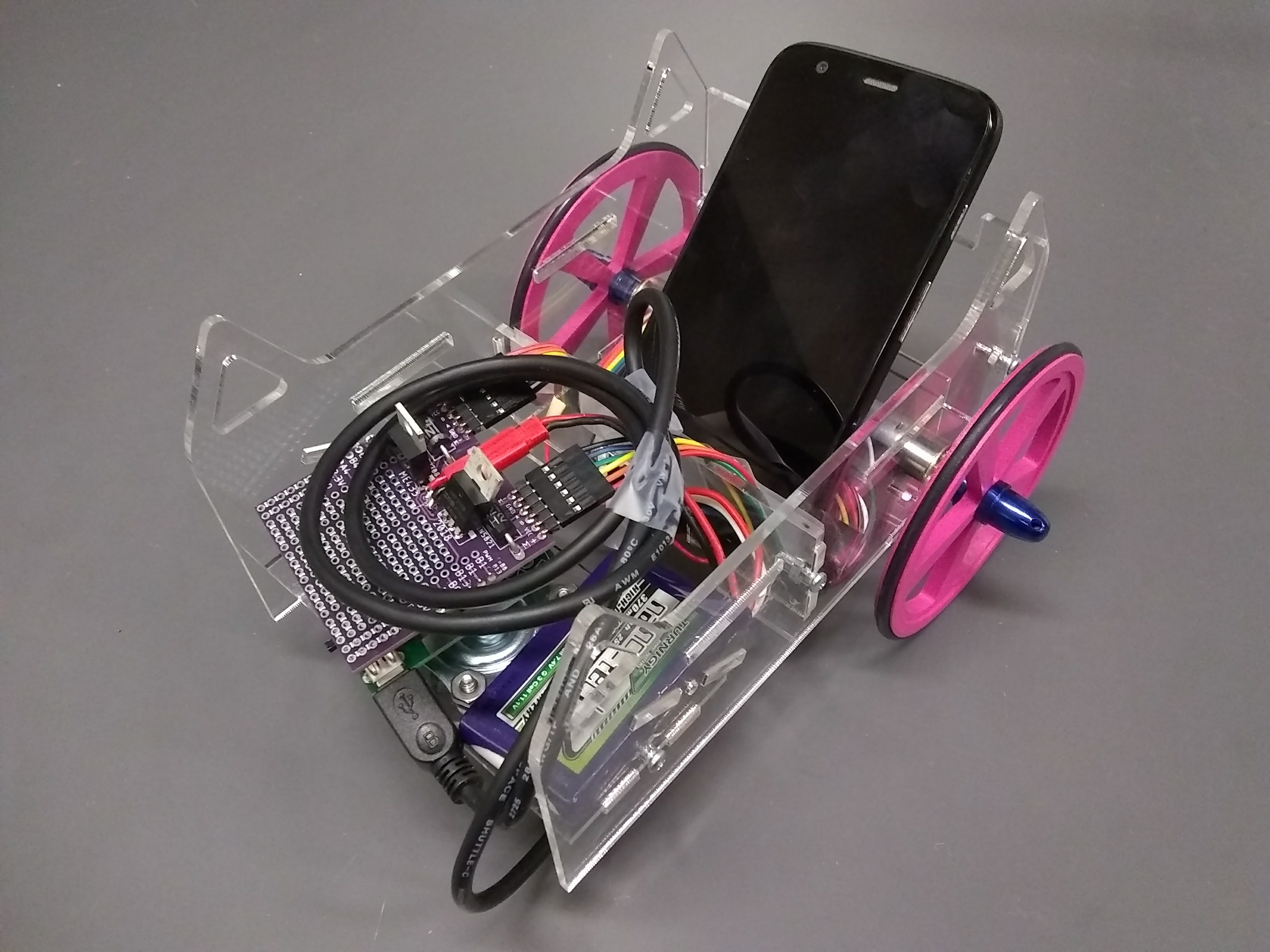
Automated Guided Car
Design & Control
About the Project
The goal of this project is to design and control a car which can follow the marked trajectory on the floor by itself without manual intervention, i.e., to design an AGV (Automated Guided Vehicle).
In this project, I can apply all the Mechatronic knowledge I've obtained previously and gain experience for designing a complete, fully-functional product.
Skills Involved
- Mechanical Design with Solidworks
- Car Construction with 3D Printing & Laser cut
- PCB Design with EAGLE
- Board Wiring
- Embedded Control in C on PIC32MX250F128B with MPLAB
- Android App Development in Java with Android Studio
- Communications via SPI & USB
- Image Processing
Hardware Used
Electronic Components
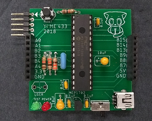
- Motion Control PCB
- 1 Microcontroller (PIC32MX250F128B)
- 2 status LEDs (one for power, one user-configurable)
- 2 push buttons (one for reset, one user-configurable)
- 1 Power switch
- 1 3.3V regulator
- 1 8MHz oscillator
- Capacitors: 4x0.1uF; 2x10uF
- Resistors: 2x10kΩ; 2x330Ω
- USB port, wires and header pins
- Motor shield PCB
- 2 Mosfets (IRF3708)
- 1 0.1 uF capacitor
- 1 battery connector
- 2 flyback diodes
Mechanical Components
- 1 universal wheel as direction guide wheel
- 2 3-inch 3D printed wheel hubs & o-rings as wheel tires
- Laser cut Acrylic chassis
- Bolts and nuts
Others
- 1 12V lithium-ion battery
- 2 12V DC motors with gearbox of ratio 63
- USB OTG adapter, Micro USB cable
- Android phone (use Moto G Black here)
Methods
It mainly consists of three sections to build the car: Mechanical design, onboard circuit design and control program design.
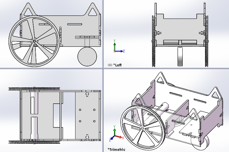
Mechanical Design
- Wheel
The wheel consists of a 3D printed wheel hub and an o-ring wrapped around as the wheel tire.
It can be easily scaled to meet different requirements.
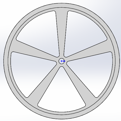
Hub
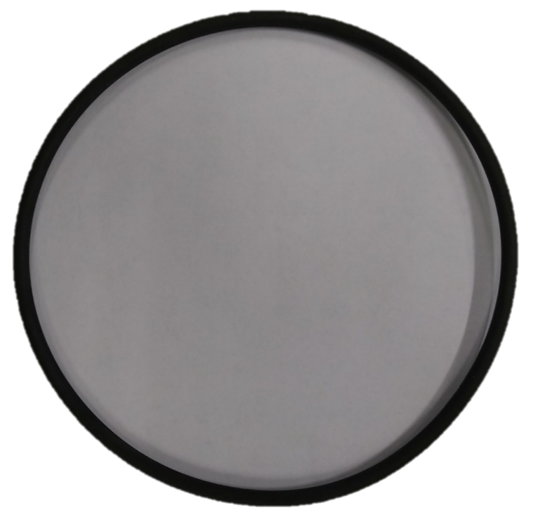
Tire
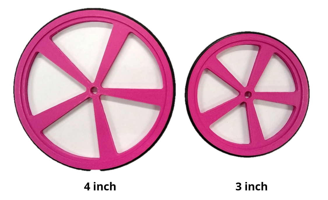
Multi Size Wheels
- Chassis
The chassis is based on 2.5D design--Use laser cut to get 2D flat boards and assemble all to construct a 3D chassis.
The model is shown at the right and the source files can be obtained in the github repository.
The boards at both sides are designed to look like the head of a cat. You can customize it to design your own chassis!
Circuit Design
I firstly drew a draft diagram for the core circuit and tested it on the breadboard. It's easy to change the layout and components with the breadboard, which makes it optimal for prototyping, but it's also too clumsy for a practical product. Something more compact and robust is needed: PCB, which is widely used in embedded systems. So after finalizing the circuit, I transferred everything to Autodesk EAGLE, a software easy to use for PCB design and free for personal use.
To design a PCB, I firstly drew the schematic diagram in EAGLE, and then reorganized and optimized the wires and sockets so that they could be fit into a 2-layer, 5cmx5cm PCB.
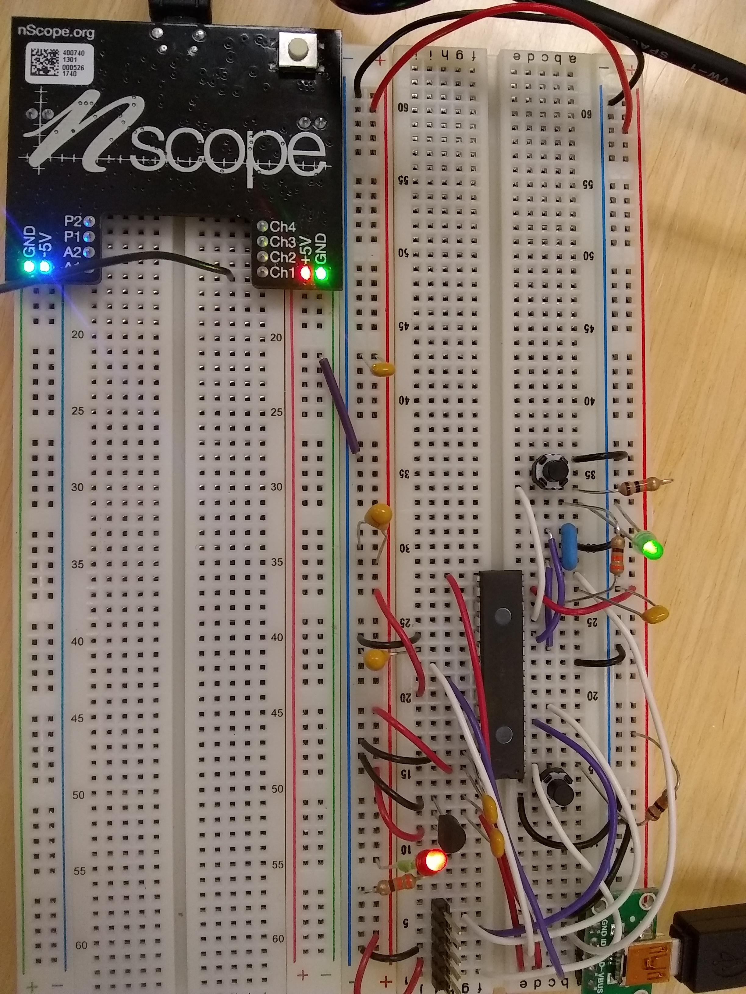
Breadboard Prototype
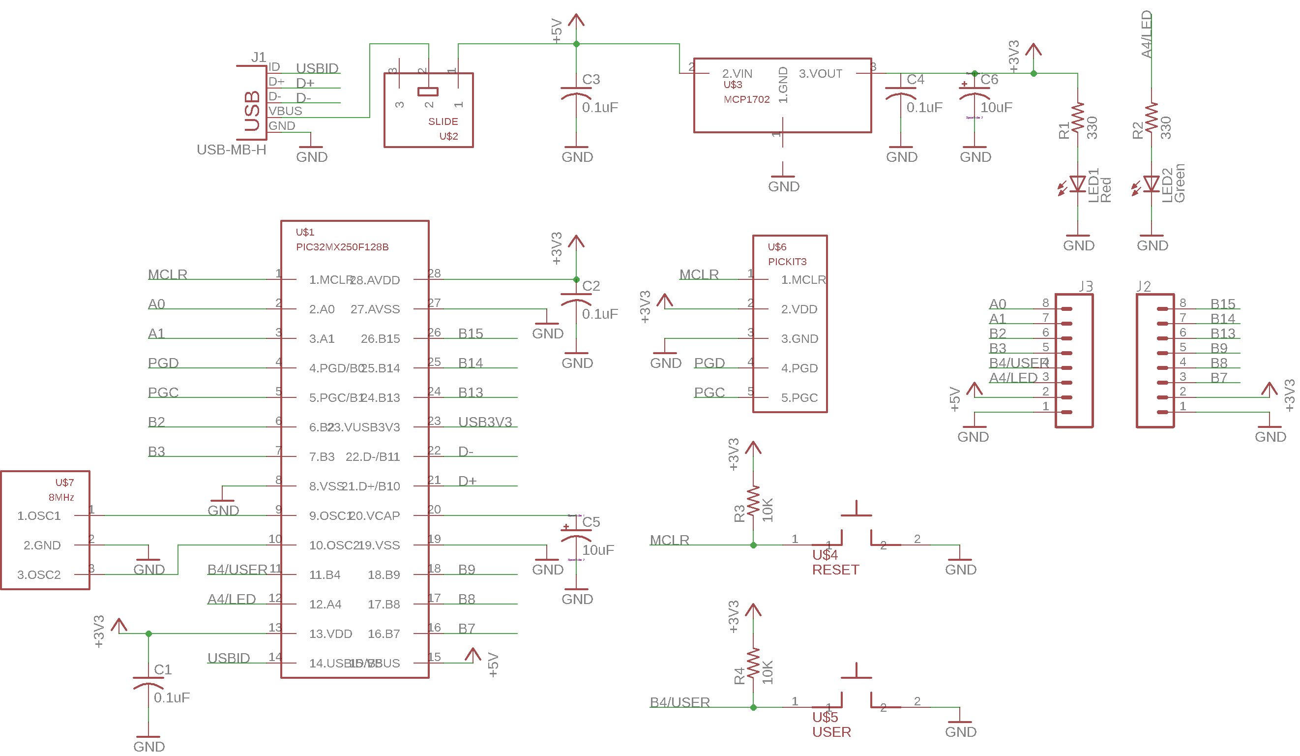
Schematic Diagram
You can also customize your PCB by writing down your name or drawing an icon. :D
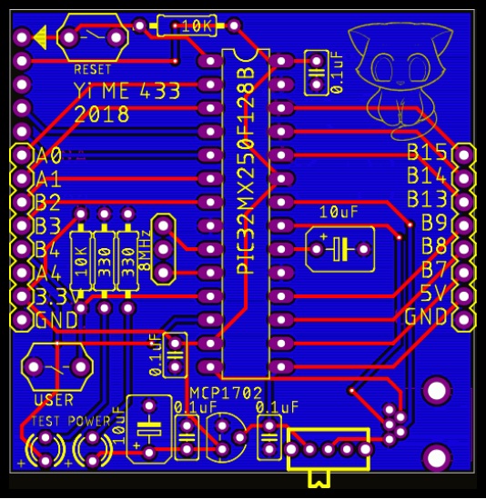
Overview
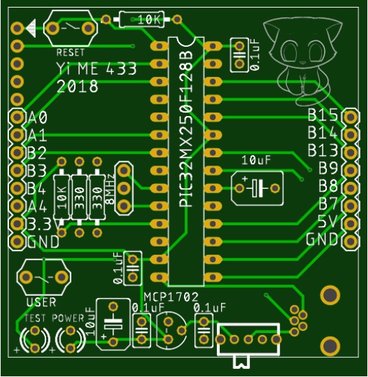
TopView
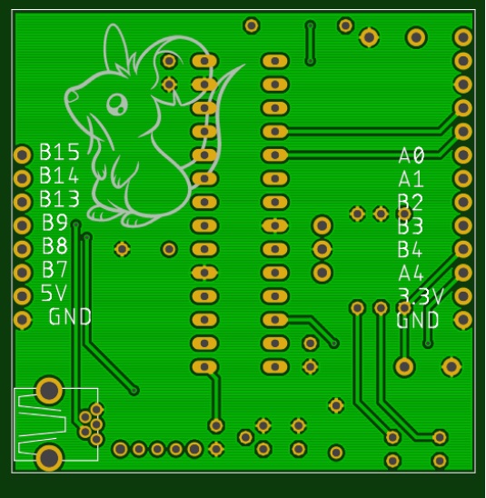
BottomView
Then attach other components (resistors, capacitors, etc) to the board and solder together.
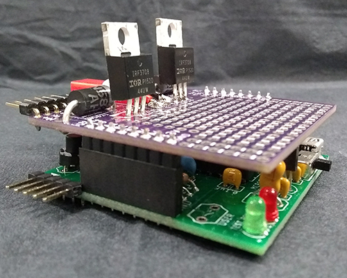
Overview
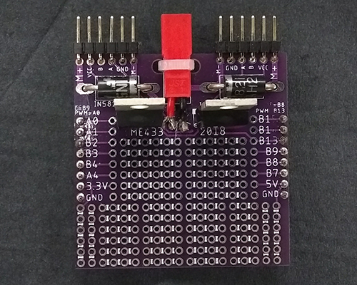
Motor Shield
Control
Software Design
It consists of embedded code written in C on the PIC32 microcontroller and an APP written in Java on the on-board phone served as monitor to locate the center of trajectory.
PIC32
- Motor Control (PI control)
- SPI commnuication
APP
- Real-time image capture
- Image Process
- Trajectory Center Calculation
Demo
A demo video to show how the car follows the trajectory is displayed below at the right. The map used is shown at the left. The gap between two ends of the line should have connected with an arch bridge, which has been moved away when recording the video.
Learn More
It's the final project for ME433: Advanced Mechatronics at Northwestern University. Refer to the repository on Github for the code and other assignments in this course.